Table of contents
Adafruit HUZZAH ESP8266 (ESP-12)
TODO: add notes
ESPresso Lite 1.0
ESPresso Lite 1.0 (beta version) is an Arduino-compatible Wi-Fi development board powered by Espressif System's own ESP8266 WROOM-02 module. It has breadboard-friendly breakout pins with in-built LED, two reset/flash buttons and a user programmable button . The operating voltage is 3.3VDC, regulated with 800mA maximum current. Special distinctive features include on-board I2C pads that allow direct connection to OLED LCD and sensor boards.
ESPresso Lite 2.0
ESPresso Lite 2.0 is an Arduino-compatible Wi-Fi development board based on an earlier V1 (beta version). Re-designed together with Cytron Technologies, the newly-revised ESPresso Lite V2.0 features the auto-load/auto-program function, eliminating the previous need to reset the board manually before flashing a new program. It also feature two user programmable side buttons and a reset button. The special distinctive features of on-board pads for I2C sensor and actuator is retained.
Phoenix 1.0
Product page: http://www.espert.co
Phoenix 2.0
Product page: http://www.espert.co
NodeMCU 0.9
Pin mapping
Pin numbers written on the board itself do not correspond to ESP8266 GPIO pin numbers. Constants are defined to make using this board easier:
static const uint8_t D0   = 16;
static const uint8_t D1   = 5;
static const uint8_t D2   = 4;
static const uint8_t D3   = 0;
static const uint8_t D4   = 2;
static const uint8_t D5   = 14;
static const uint8_t D6   = 12;
static const uint8_t D7   = 13;
static const uint8_t D8   = 15;
static const uint8_t D9   = 3;
static const uint8_t D10  = 1;
If you want to use NodeMCU pin 5, use D5 for pin number, and it will be translated to 'real' GPIO pin 14.
NodeMCU 1.0
This module is sold under many names for around $6.50 on AliExpress and it's one of the cheapest, fully integrated ESP8266 solutions.
It's an open hardware design with an ESP-12E core and 4 MB of SPI flash.
Acording to the manufacturer, "with a micro USB cable, you can connect NodeMCU devkit to your laptop and flash it without any trouble". This is more or less true: the board comes with a CP2102 onboard USB to serial adapter which just works, well, the majority of the time. Sometimes flashing fails and you have to reset the board by holding down FLASH + RST, then releasing FLASH, then releasing RST. This forces the CP2102 device to power cycle and to be re-numbered by Linux.
The board also features a NCP1117 voltage regulator, a blue LED on GPIO16 and a 220k/100k Ohm voltage divider on the ADC input pin.
Full pinout and PDF schematics can be found here
Olimex MOD-WIFI-ESP8266-DEV
This board comes with 2 MB of SPI flash and optional accessories (e.g. evaluation board ESP8266-EVB or BAT-BOX for batteries).
The basic module has three solder jumpers that allow you to switch the operating mode between SDIO, UART and FLASH.
The board is shipped for FLASH operation mode, with jumpers TD0JP=0, IO0JP=1, IO2JP=1.
Since jumper IO0JP is tied to GPIO0, which is PIN 21, you'll have to ground it before programming with a USB to serial adapter and reset the board by power cycling it.
UART pins for programming and serial I/O are GPIO1 (TXD, pin 3) and GPIO3 (RXD, pin 4).
You can find the board schematics here
Olimex MOD-WIFI-ESP8266
This is a stripped down version of the above. Behaves identically in terms of jumpers but has less pins readily available for I/O. Still 2 MB of SPI flash.
Olimex ESP8266-EVB
It's a Olimex MOD-WIFI-ESP8266-DEV module installed on the headers of a development board which features some breakout connectors, a button (GPIO0) and a relay (GPIO5).
Programming is pretty straightforward: the board is supported in the Arduino IDE after installing it via the Board Manager. To download a program you just have to connect GND/RX/TX from a serial/USB adapter to the UEXT connector and press the only button before applying power to enter UART mode.
Don't connect 5V from the serial/USB adapter to the board or you won't be able to power cycle it for UART mode.
You can find the board schematics here.
This guide is also useful for the first setup, since it contains the UEXT connector pinout.
Board variants include: * ESP8266-EVB-BAT: comes with built-in LiPo charger and step-up converter * ESP8266-EVB-BAT-BOX: as above, but enclosd in a plastic box (non-weatherproof)
SparkFun ESP8266 Thing
Product page: https://www.sparkfun.com/products/13231
TODO: add notes
SweetPea ESP-210
TODO: add notes
ESPino
ESPino integrates the ESP-12 module with a 3.3v regulator, CP2104 USB-Serial bridge and a micro USB connector for easy programming. It is designed for fitting in a breadboard and has an RGB Led and two buttons for easy prototyping.
For more information about the hardware, pinout diagram and programming procedures, please see the datasheet.
Product page: http://www.espino.io/en
WifInfo
WifInfo integrates the ESP-12 or ESP-07+Ext antenna module with a 3.3v regulator and the hardware to be able to measure French telemetry issue from ERDF powering meter serial output. It has a USB connector for powering, an RGB WS2812 Led, 4 pins I2C connector to fit OLED or sensor, and two buttons + FTDI connector and auto reset feature.
For more information, please see WifInfo related blog entries, github and community forum.
Generic ESP8266 modules
These modules come in different form factors and pinouts. See the page at ESP8266 community wiki for more info: ESP8266 Module Family.
Usually these modules have no bootstapping resistors on board, insufficient decoupling capacitors, no voltage regulator, no reset circuit, and no USB-serial adapter. This makes using them somewhat tricky, compared to development boards which add these features.
In order to use these modules, make sure to observe the following:
Provide sufficient power to the module. For stable use of the ESP8266 a power supply with 3.3V and >= 250mA is required. Using the power available from USB to Serial adapter is not recommended, these adapters typically do not supply enough current to run ESP8266 reliably in every situation. An external supply or regulator along with filtering capacitors is preferred.
Connect bootstapping resistors to GPIO0, GPIO2, GPIO15 according to the schematics below.
Put ESP8266 into bootloader mode before uploading code.
Serial Adapter
There are many different USB to Serial adapters / boards. To be able to put ESP8266 into bootloader mode using serial handshaking lines, you need the adapter which breaks out RTS and DTR outputs. CTS and DSR are not useful for upload (they are inputs). Make sure the adapter can work with 3.3V IO voltage: it should have a jumper or a switch to select between 5V and 3.3V, or be marked as 3.3V only.
Adapters based around the following ICs should work:
- FT232RL
- CP2102
- CH340G
PL2303-based adapters are known not to work on Mac OS X. See https://github.com/igrr/esptool-ck/issues/9 for more info.
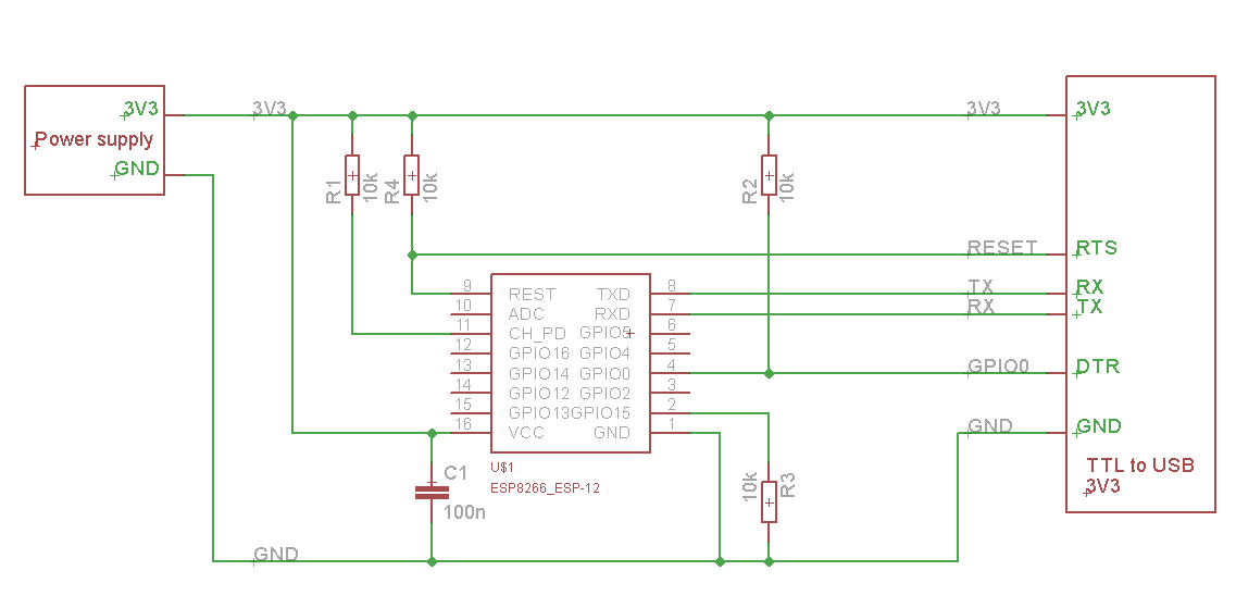
Minimal Hardware Setup for Bootloading and Usage
| PIN | Resistor | Serial Adapter |
|---|---|---|
| VCC | VCC (3.3V) | |
| GND | GND | |
| TX or GPIO2* | RX | |
| RX | TX | |
| GPIO0 | PullUp | DTR |
| Reset* | PullUp | RTS |
| GPIO15* | PullDown | |
| CH_PD | PullUp |
- Note
- GPIO15 is also named MTDO
- Reset is also named RSBT or REST (adding PullUp improves the stability of the module)
- GPIO2 is alternative TX for the boot loader mode
- Directly connecting a pin to VCC or GND is not a substitute for a PullUp or PullDown resistor, doing this can break upload management and the serial console, instability has also been noted in some cases.
ESP to Serial
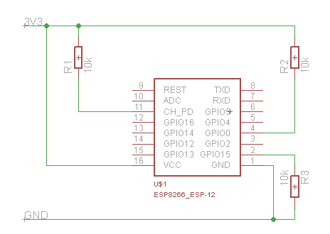
Minimal Hardware Setup for Bootloading only
ESPxx Hardware
| PIN | Resistor | Serial Adapter |
|---|---|---|
| VCC | VCC (3.3V) | |
| GND | GND | |
| TX or GPIO2 | RX | |
| RX | TX | |
| GPIO0 | GND | |
| Reset | RTS* | |
| GPIO15 | PullDown | |
| CH_PD | PullUp |
- Note
- if no RTS is used a manual power toggle is needed
Minimal Hardware Setup for Running only
ESPxx Hardware
| PIN | Resistor | Power supply |
|---|---|---|
| VCC | VCC (3.3V) | |
| GND | GND | |
| GPIO0 | PullUp | |
| GPIO15 | PullDown | |
| CH_PD | PullUp |
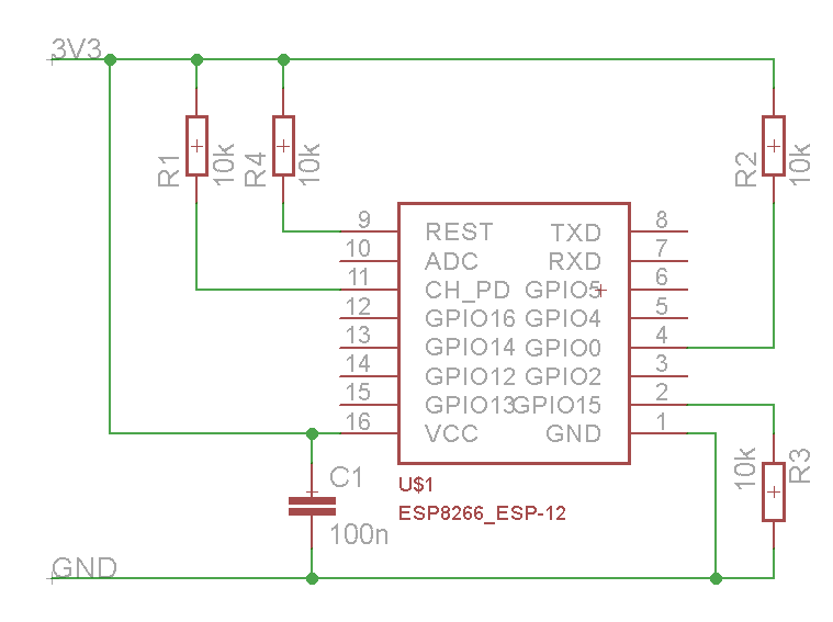
Minimal
Improved Stability
Boot Messages and Modes
The ESP module checks at every boot the Pins 0, 2 and 15. based on them its boots in different modes:
| GPIO15 | GPIO0 | GPIO2 | Mode |
|---|---|---|---|
| 0V | 0V | 3.3V | Uart Bootloader |
| 0V | 3.3V | 3.3V | Boot sketch (SPI flash) |
| 3.3V | x | x | SDIO mode (not used for Arduino) |
at startup the ESP prints out the current boot mode example:
rst cause:2, boot mode:(3,6)
note: - GPIO2 is used as TX output and the internal Pullup is enabled on boot.
rst cause
| Number | Description |
|---|---|
| 0 | unknown |
| 1 | normal boot |
| 2 | reset pin |
| 3 | software reset |
| 4 | watchdog reset |
boot mode
the first value respects the pin setup of the Pins 0, 2 and 15.
| Number | GPIO15 | GPIO0 | GPIO2 | Mode |
|---|---|---|---|---|
| 0 | 0V | 0V | 0V | Not valid |
| 1 | 0V | 0V | 3.3V | Uart |
| 2 | 0V | 3.3V | 0V | Not valid |
| 3 | 0V | 3.3V | 3.3V | Flash |
| 4 | 3.3V | 0V | 0V | SDIO |
| 5 | 3.3V | 0V | 3.3V | SDIO |
| 6 | 3.3V | 3.3V | 0V | SDIO |
| 7 | 3.3V | 3.3V | 3.3V | SDIO |
note: - number = ((GPIO15 << 2) | (GPIO0 << 1) | GPIO2);
Generic ESP8285 modules
ESP8285 (datasheet) is a multi-chip package which contains ESP8266 and 1MB flash. All points related to bootstrapping resistors and recommended circuits listed above apply to ESP8285 as well.
Note that since ESP8285 has SPI flash memory internally connected in DOUT mode, pins 9 and 10 may be used as GPIO / I2C / PWM pins.
WeMos D1
Product page: http://wemos.cc
WeMos D1 mini
Product page: http://wemos.cc
ESPino (WROOM-02 Module) by ThaiEasyElec
ESPino by ThaiEasyElec using WROOM-02 module from Espressif Systems with 4 MB Flash.
We will update an English description soon. - Product page: http://thaieasyelec.com/products/wireless-modules/wifi-modules/espino-wifi-development-board-detail.html - Schematics: www.thaieasyelec.com/downloads/ETEE052/ETEE052_ESPino_Schematic.pdf - Dimensions: http://thaieasyelec.com/downloads/ETEE052/ETEE052_ESPino_Dimension.pdf - Pinouts: http://thaieasyelec.com/downloads/ETEE052/ETEE052_ESPino_User_Manual_TH_v1_0_20160204.pdf (Please see pg. 8)